What is GeoPop Pro?
What can you do with the GeoPop Pro Tool?
Quick Reference Guide
Editing in the JTX Environment
Tool Controls
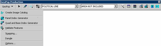
GeoPop Pro Menu
![]() Create Image Catalog
Create Image Catalog
![]() Panel Index Generator
Panel Index Generator
![]() Base and Quad Index Generator
Base and Quad Index Generator
![]() Validate Features
Validate Features
Snapping
Dangle
Options
![]() Edit
Edit
![]() Create New Feature
Create New Feature
![]() Trace
Trace
![]() Construct Features
Construct Features
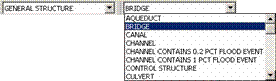
Target Layer
Feature Type
![]() Snap Tolerance
Snap Tolerance
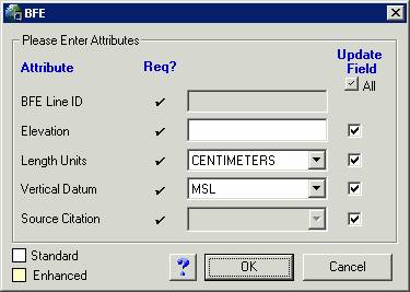
![]() Attributes
Attributes
![]() Add New Row
Add New Row
![]() Attribute Selected Features
Attribute Selected Features
![]() Attribute All Selected Features
Attribute All Selected Features
![]() Panel Divider
Panel Divider
![]() Panel Merger
Panel Merger
Load Additional Data Toolbar
![]() DFIRM Layer Data Loader
DFIRM Layer Data Loader
![]() DFIRM Reference Data Loader
DFIRM Reference Data Loader
![]() Show DFIRM Adjacent Area
Show DFIRM Adjacent Area
![]() Show Only DFIRM Area
Show Only DFIRM Area
Trouble – Shooting
Contacts
The Federal Emergency Management Agency’s (FEMA) April 2003 Appendix L: Guidelines and Specifications for Flood Hazard Partners (hereon after referred to as FEMA’s database specifications) includes the specifications for both draft and delivered DFIRM data. The Geodatabase Population (GeoPop Pro) Tool is a user-friendly application designed to run within ArcMap that allows you to easily capture and edit data that meets FEMA’s draft DFIRM database specifications.
With this application, you can easily edit geodatabases with feature classes, domains, and business tables that are compliant with FEMA’s database specifications. An advantage of this application is that it prompts you to attribute features as they are digitized. Another advantage is that the dropdown options on the attribute forms are read directly from the domain tables and look-up business tables.
The design of this application consists of a toolbar that is accessible through ArcMap. Each tool on the toolbar helps to simplify data capture. Many tools are similar to existing ArcMap tools for easy recognition: however, they have different functionality. For instance, the GeoPop Pro Create New Feature tool allows you to attribute each feature as it is created. There are also tools included for convenience that have not been modified, such as the Snap Tolerance tool.
|
| You can attribute features as you digitize by using the Create New Feature tool. |
|
You can validate attributes of selected features using the Validate Features tool. |
|
| You can attribute a selected set of features individually using the Attribute Selected Features tool, or you can attribute all of the selected features the same way using the Attribute All Selected Features tool. |
 |
You can set the snapping tolerance using the Snap Tolerance tool. |
|
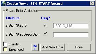
| You can add a record to one of the look-up tables using the Add New Row tool. |
|
You can merge the FIRM Panel Index panels using the Panel Merger tool. |
|
| You can create new features using existing features in the same layer with the Trace tool. |
|
You can split the FIRM Panel Index panels into quarters using the Panel Divider tool. |
|
| You can create new features based on the shape of the features in another layer using the Construct Features tool. |
|
You can view the attributes of selected features using the Attributes tool. |
|
| You can generate panels for the FIRM Panel Index (S_FIRM_Pan) using the Panel Index Generator tool. |
|
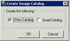
You can create raster catalogs using the Create Image Catalog tool. This creates a raster catalog from all the images located in a folder. |
|
| You can select the type of feature to sketch using the Feature Type drop down tool. |
 |
Select the feature layer to edit using the Target Layer drop down tool. This will also set the target layer as the only selectable layer. | |
The following is a quick reference guide to all the tools available in the GeoPop Pro Tool. In addition, positioning your cursor over a button on the toolbar will display its name.
|
|
Edit | Edits features |
|
|
Create New Feature | Adds points to sketch |
|
|
Trace | Trace features |
| Target Layer | Identifies which map layer to store features | |
| Feature Type | Identifies the type of feature to digitize | |
|
|
Construct Features | Creates features based on selected features |
|
|
Create Image Catalog | Creates catalog |
|
|
Panel Index Generator | Generates panels for FIRM Panel Index |
| Validate Features | Validates features | |
| Snapping | Shows snapping environment window | |
| Dangle | Shows dangle window | |
| Options | Modify the snapping environment | |
|
|
Attributes | Shows attribute properties |
|
|
Add New Row | Edits tables |
|
|
Attribute All Selected Features | Attributes all selected features |
|
|
Attribute Selected Features | Attributes selected features individually |
|
|
Snap Tolerance | Sets snap tolerance |
|
|
Panel Merger | Merges Selected Panels |
|
|
Panel Divider | Splits Selected Panel |
| About | Displays program information |
Many of the tools available in GeoPop require that you start an editing session. When you start an editing session, you may see the following dialog:
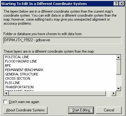
The dialog box warns you that the version of the data that you are planning to edit is stored in a different projection than that which it is displayed in the ArcMap project. The ArcMap session in which you are working projects the data based on the entry made in the STUDY_INFO table and the data is stored in geographic. Click on Start Editing to accept the warning.
This section describes the functionality of each of the tools on the GeoPop Pro toolbar.
This button opens the drop down menu containing menu items that allow you to validate features and to set snapping and editing options.
From the GeoPop Pro toolbar, click GeoPop Pro menu to display the menu items.
This tool creates an image catalog from the images located in a directory. To display the catalog, the layer must first be added using the DFIRM Reference Data Loader button.
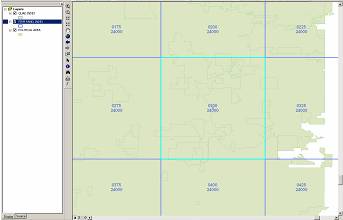
Generates FIRM Panel Index (S_FIRM_Pan) panel areas based on the extent of the Political Area (S_Pol_Ar). When you use the Panel Index Generator tool, certain fields such as panel number and scale will be automatically calculated for you. This tool requires that the Political Area (S_Pol_Ar) data layer is created and populated in advance. The panels created are limited to the extent of the Political Area.
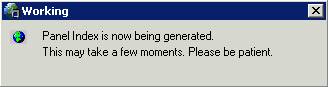
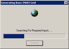
The tool will now begin the process of generating FIRM Panel Index (S_FIRM_Pan) panel areas. The following window will appear. It may take a few moments to complete. This window will disappear when the process has completed.
|
| Generating S_FIRM_Pan and S_Quad_Index using the Panel Index Generator |
Note: It is important that you attribute the FIRM Panel features after generating them. While some attributes are calculated automatically upon creation, there are others that the user will have to enter for additional DFIRM tools to function.
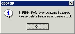
If any features already exist in the FIRM Panel Index (S_FIRM_Pan), the following error message will appear. You must remove any existing features before re-running the tool.
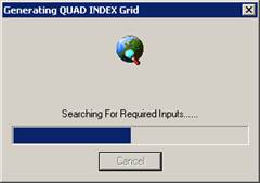
Generates Base Index (S_BASE_INDEX) and Quad Index (S_QUAD_INDEX) based on your study data. For Base Index, the tool looks to the appropriate folder which contains the base images used for the study. Any image that resides in that folder is added to the Base Index. For Quad Index, the tool uses the Political Area features to select the appropriate panels from a nationwide shapefile of USGS 7.5 minute Quads. During this process, the user is prompted to set attribute information for the features being created, as outlined below.
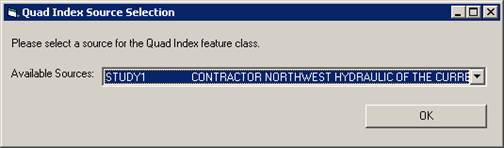
Note: The Available Sources dropdown menu is populated by L_SOURCE_CIT. If the source that you need is not present in the list, then you will have to go back and use GeoPop to add and additional source to L_SOURCE_CIT.
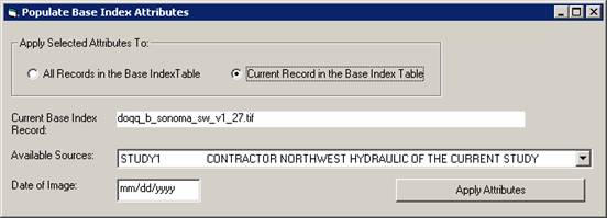
Note: The Available Sources dropdown menu is populated by L_SOURCE_CIT. If the source that you need is not present in the list, then you will have to go back and use GeoPop to add and additional source to L_SOURCE_CIT.
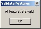
Applies validation rules to selected features in a geodatabase and flags those features with invalid attributes.
If your selection contains any invalid features, a message box will appear with the number of invalid features. Only those features that are invalid will remain selected, as seen in the following image:
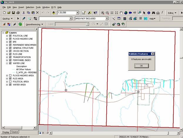
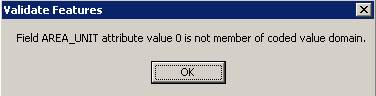
A message box appears telling you why the feature is invalid.
|
| Attributes window seen in ArcMap |
|
| Validate Selection results window seen in ArcMap |
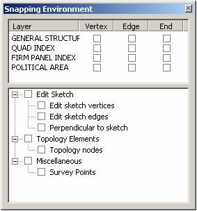
Opens and closes the Snapping Environment window. Snapping allows the user to designate if the edited feature will connect to the vertex, edge, or end of another feature. The user may also elect whether the feature being edited is able to snap to its own edge or vertex. The order of the feature layers defines the priority of the snapping. By dragging layers up and down in the Table of Contents, the snapping priority will change. Note that when the Snapping Environment window is closed, the snap-related properties are still active; the user must unselect the relative checkboxes to discontinue snapping.
The snapping properties are effective as soon as they are checked or unchecked.
|
| Snapping environment window seen in ArcMap |
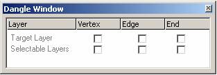
Opens and closes the Dangle environment window. This tool allows the user to display dangle-related errors. If the selected polyline features are not connected to the vertex, edge, or end of another polyline feature, the node is highlighted. The user may choose to display errors for the target layer, which must have a polyline geometry type, or may choose to display errors in all selectable polyline geometry types. Note that when the Dangle Window is closed, the dangle-related properties are still active; the user must unselect the relative checkboxes to no longer display the dangle nodes.
Note: This tool is especially useful for snapping flood zone lines together and for snapping BFEs to the 100-year flood zone.
Displays the options for the ArcMap editing environment. Most of the time, you will only use the options that appear under the General tab.
It is recommended to set the units of snapping tolerance to map units.
The editing properties are effective immediately.
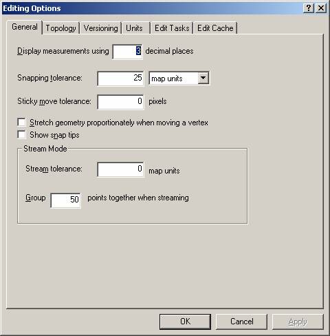
|
| Editing Options dialog window |
Selects geographic features for the purpose of editing. You can click on a feature to select it or drag a box to select many features.
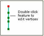
|
| Modifying vertices of a feature in ArcMap |
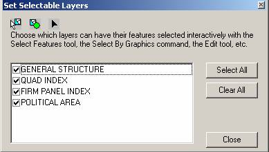
|
| Set Selectable Layers window seen in ArcMap |
Adds points, vertices, and segments to the sketch. You can create three types of features: points, lines, and polygons.
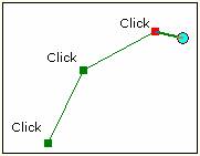
|
| Creating new features in ArcMap |
TIP: Use snapping to ensure connectivity.
The dropdown lists contain the coded value descriptions for the related fields, which are populated from the tables inside the geodatabase. Changes to the tables in the geodatabase will affect the list that appears in the dropdown.
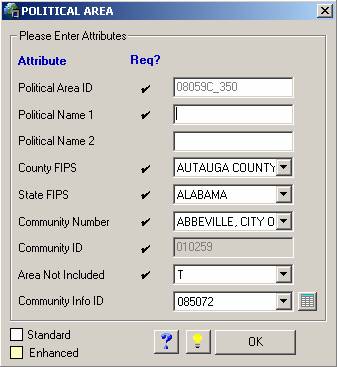
|
NOTES: Standard attributes are displayed with white field backgrounds.
Enhanced attributes have yellow field backgrounds. Checkmarks in the “Required ” column indicate those fields that must be populated. |
| Attribute feature window seen in ArcMap. Note: Attribute dialogs will vary depending on target layer | |
Creates segments by tracing over the segments of selected features.
You can move the mouse in the reverse direction to remove unwanted segments or press the Esc key to cancel the trace.
|
| Tracing features in ArcMap. No offset is used in this example. |
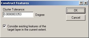
Constructs features based on the shape of selected features. You can select features from one or more layers to create features in the target layer. You can choose to select lines or polygons to create lines or polygons depending on the geometry of the target layer. This command is disabled if you have an ArcView license.
|
|
| Target Layer |
|
| Setting the cluster tolerance for Construct Features command in ArcMap |
Sets the map layer that contains the features you want to edit or store new features to. In setting the target layer, the Feature Type dropdown is enabled/disabled based on whether the target layer has multiple feature types that can be digitized.
The Target Layer window should be active.
|
|
| Target Layer |
|
| Setting the target layer in ArcMap |
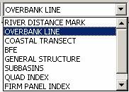
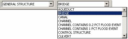
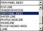
Specifies the feature type that will be digitized. This tool is only enabled when the current edit layer is either: Flood Hazard Line (S_Fld_Haz_Ln), General Structure (S_Gen_Struct), PLSS Line (S_PLSS_Ln), Political Line (S_Pol_Ln), Transportation (S_Trnsport_Ln), or Water Line (S_Wtr_Ln). The tool will not be enabled if any other layer is currently being edited.
| Target Layer | Feature Type |
|
|
| Setting Feature Type command in ArcMap | |
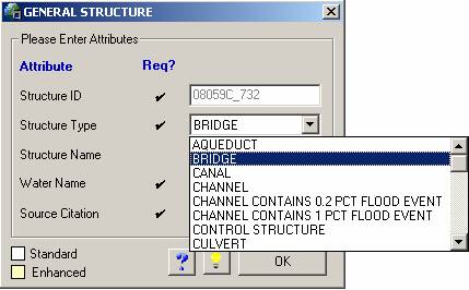
You will notice that the feature type selected is reflected in the attribute feature dialog window. The feature type can be modified before the attributes are applied to the feature.
|
NOTES: Standard attributes are displayed with white field backgrounds.
Enhanced attributes have yellow field backgrounds. Checkmarks in the “Required” column indicate those fields that must be populated. |
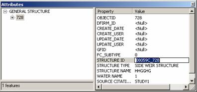
| Attribute feature window for the General Structures layer | |
Sets the tolerance value applied to all snap agents.

The tolerance units and value can also be set in the Options window.
Allows attributes of selected features to be viewed and modified. This tool is useful for viewing data and making edits. To have more control over attribute editing and to take advantage of intuitive dropdown options for fields with domains and look-up tables, it is recommended that you use either the Attribute Selected Features or the Attribute All Selected Features tool.
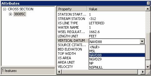
|
| Attributes window |
Adds new records to the tables. Currently, this tool works for the non-feature attribute tables (L_) and Study_Info.
|
| Table of contents frame in ArcMap |
|
NOTES: Standard attributes are displayed with white field backgrounds.
Enhanced attributes have yellow field backgrounds. Checkmarks in the “Required” column indicate those fields that must be populated. |
| Add New Row attribute window | |
Note: To view the tables listed in the table of contents, click on the Source tab located at the bottom left of the viewer window.
Attributes selected features using the attribute dialog windows.
The feature attribute window will appear.
The attribute window displays the current attributes of the feature. If the feature does not have any attributes, default attributes will be shown.
Attributes all selected features using dialog windows. All selected features will be attributed with the same values.
Note: Attribute All Selected Features will apply the same attributes to all of the selected features. Attribute Selected Features permits you to apply unique attributes to features, even if you select more than one at a time. Also note that your edits will be saved automatically. You will not be prompted to “Save Edits” when you stop editing.
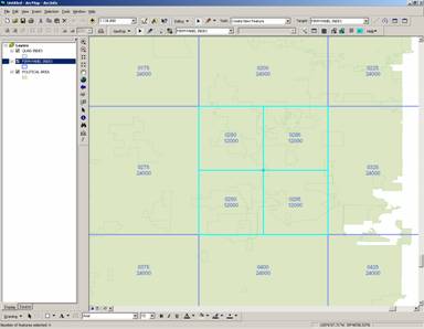
Panel Divider enables you to divide a FIRM Panel Index (S_FIRM_Pan) panel into quarters. You can split a 1:24,000 scale panel into four 1:12,000 panels, or you can split a 1:12000 panel into four 1:6,000 panels. The scales mentioned are those displayed in ArcMap. The scale shown on panel layouts will be displayed in feet. The tool also automatically calculates the new panel numbers, scales, and corner coordinates.
Note: If you want to turn on labels for this process, you need to right-click on “FIRM PANEL INDEX” in the table of contents. Next, select “Properties…”, then select the “Label” Tab. Then, check the “Label features in this layer” box and select the “Expression” tab. In the “Expression” window, type [PANEL] & vbnewline & [SCALE]. This will label each FIRM Panel with the panel number and scale as seen in the images below.
|
Each panel shows the Panel ID number above the Panel Scale (in inches) |
| Selecting features to split using the Panel Divider tool in ArcMap | |
|
Each panel shows the Panel ID number above the Panel Scale (in inches) |
| The results of the Panel Divider command | |
You should see the panels divided into quarters with the panels and scale correctly attributed.
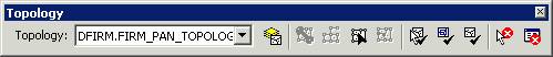
Note: It is critical that you validate the topology after each use of the Panel Divider. If you do not validate after each edit, there will be errors in the topology (gaps and slivers) and resulting error messages will follow.
|
| Validate Topology in Current Extent |
|
| Validating Topology status box |
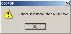
NOTE: The Panel Divider tool will not allow you to create panels smaller than 6,000-scale. You will see the following window if you attempt to divide a 6,000-scale panel.
|
| Error message shown when trying to split panels smaller than 6000-scale |
The Panel Merger tool enables you to merge two or more selected FIRM Panel Index (S_FIRM_Pan) panels to create custom panels. The tool automatically calculates the new panel number and scale. It also checks to make sure duplicate panels are not created in the merging operation. For example, if a 24,000-scale panel exists, it will not create another.
The Panel Merger tool allows you to merge multiple panels within the extent of a 1:24,000 scale panel into one panel. However, it will not allow you to merge panels across 24,000-scale panels, nor will it merge 6,000-scale panels across 12,000-scale panels.
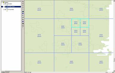
|
| Merging panels using the Panel Merger command in ArcMap |
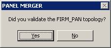
|
| Confirm that you have validated the topology |
If you select Yes, then the panels will merge. However if you select No, the tool will not merge the panels, giving you the chance to properly validate your features. You should see the panels merged and scale correctly attributed.
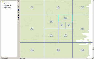
|
| The results of the Panel Merger command |
|
|
| Validate Topology in Current Extent |
|
|
| Validating Topology status box |
The tools on the Load Additional Data Toolbar allow users to add data to their ArcMap session that is not added automatically as part of the standard DFIRM layers. Data that a user may wish to add includes raster catalogs of DOQs/Quads, contour lines, effective panel layout schemes, and any of the enhanced SDE feature classes.
|
|
DFIRM Layer Data Loader | Adds additional layers and tables from the SDE geodatabase |
|
|
DFIRM Reference Data Loader | Adds reference data to the map view |
|
|
Show DFIRM Adjacent Area | View adjacent DFIRMs |
|
|
Show Only DFIRM Area | Remove view of adjacent DFIRMs |
Available Data Layers: list of features that are part of
the SDE geodatabase that can be added. |
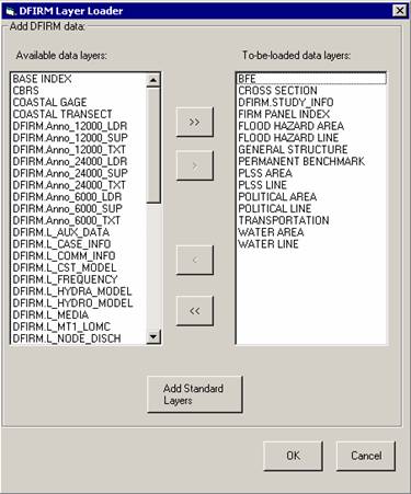 |
To-be-loaded data layers: list of all features that will be added to ArcMap. |
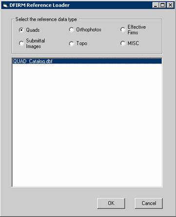
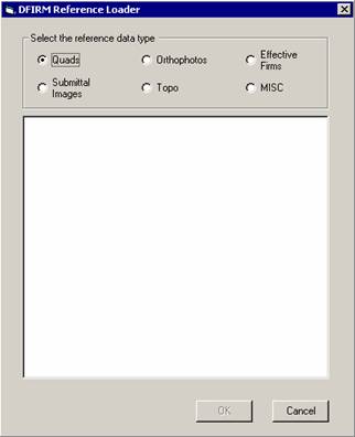
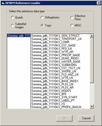
Used to add any additional reference data that does not reside in the SDE geodatabase. This includes: raster catalogs (DOQs or USGS Quads), topo (contour lines), and effective map layouts.
Select type of reference data to load: |
|
If the user selects the “Topo” or “MISC” radio button, then they will receive the following message:
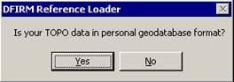
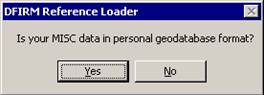
If the user selects “Yes”, then the dialog changes to the following, where the user can pick the personal geodatabase and then will be able to choose the feature classes from that geodatabase:
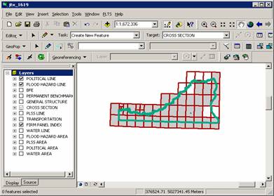
Click on this button to show data for adjacent areas. If data for adjacent areas is loaded into the database, it will be shown. You will not have permission to edit any data in an adjacent area; it is only shown for your reference. Once you select the button, its icon will change to that of the Show Only DFIRM Area tool.
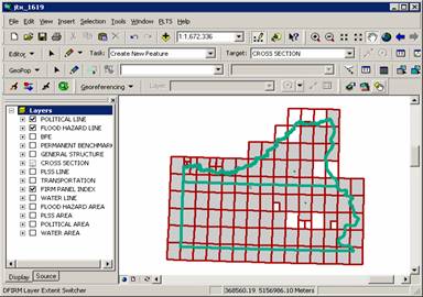
Click on this button to remove data showing for adjacent areas. Once you select the button, adjacent data will disappear and the button icon will change to that of the Show DFIRM Adjacent Area tool (see above).
Problem: Feature Type tool is enabled and not displaying any line types.
Solution: Make sure that you use the Target Layer dropdown item on the GeoPop Pro toolbar when you start an edit session.
Problem: Attribute dialog boxes do not appear after a new sketch has been created.
Solution: Make sure that you double-click to finish creating a new sketch.
Problem: The Panel Index Generator doesn’t work.
Solution: Verify that the corporate limits or political layer (S_Pol_Ar) is loaded. If it does not appear in the table of contents, add it to your project using the DFIRM Layer Data Loader.
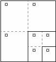
Problem: When splitting and merging panels, a panel will not merge properly.
Solution: Try performing the splitting and merging of panels in a different order. For instance, if you wanted to make the panel layout shown in the diagram below, there are several ways you could create it. You could do the panel splitting work first and then the merging. Alternatively, you could split the large panel, merge three of the resulting panels and then repeat the process with the fourth panel.
Problem: The following error message appears:
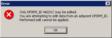
Solution: You are restricted to editing data that has the same DFIRM ID as the job on which you are working. When you click on OK to accept the message, your editing session will be terminated automatically.
Problem: I cannot add a feature to a feature class that is visible (there is a black checkmark in the box next to the name). I have made sure that the layer is selectable.
Solution: Some layers have scale dependencies set on them to prevent the addition of features if the scale of the map is too small. Zoom in to a larger scale, such as 1:3000, and try to add the feature with the GeoPop tools.
Problem: I digitized several features, but when I open the attribute table, many of the fields are “<NULL>”.
Solution: Make sure that you are using the tools on the GeoPop toolbar, and not the tools on the Editor toolbar. Also, be sure to wait for the attribute dialog box to open after each feature you create. This will ensure you are attributing all features correctly.
If you need assistance with this tool, please contact the representative at your local RMC.
| NAME | ROLE | PHONE | |
|---|---|---|---|
| REGION I | |||
| Brent McCarthy | Lead | Brent.McCarthy@mapmodteam.com | (336) 240-7339 |
| Jeffrey Burm | GIS/Mapping | JeffBurm@mapmodteam.com | (517) 482-4930 x4752 |
| REGION II | |||
| Rich Cassin | Operations Manager | Rich.Cassin@mapmodteam.com | (914) 333-5366 |
| Michael Crino | GIS/Mapping | mcrino@mbakercorp.com | (718) 482-9945 |
| REGION III | |||
| Mike Conaboy | Operations Manager | mconaboy@mbakercorp.com | (609) 734-7922 |
| Lee Brancheau | Senior GIS Manager | lbrancheau@mbakercorp.com | (609) 734-7912 |
| REGION IV | |||
| Stephen King | Operations Manager | Stephen.King@mapmodteam.com | (678) 459-1010 |
| Kagan Kuyu | GIS/Mapping | Kagan.Kuyu@mapmodteam.com | (678) 459-1041 |
| REGION V | |||
| Sujata Banerjee | Business Manager | Sujata.Banerjee@mapmodteam.com | (312) 575-3902 |
| Pam Coye | GIS/Mapping | Pam.Coye@mapmodteam.com | (312) 575-3913 |
| REGION VI | |||
| Dan Hoecker | Operations Manager | Dan.Hoecker@mapmodteam.com | (940) 783-4155 |
| Phil Nguyen | GIS/Mapping | pxnguyen@mbakercorp.com | (940) 783-4121 |
| REGION VII | |||
| Matthew Koch | Operations Manager | mkoch@watershedconcepts.com | (816) 502-9420 x4952 |
| Rod Odom | GIS/Mapping | rodom@watershedconcepts.com | (816) 502-9420 x4957 |
| REGION VIII | |||
| David Jula | Operations Manager | David.Jula@mapmodteam.com | (720) 514-1100 |
| Mike Garner | GIS/Mapping | Mike.Garner@mapmodteam.com | (720) 514-1105 |
| REGION IX | |||
| Travis Clark | Business Manager | Travis.Clark@mapmodteam.com | (510) 879-0950 |
| Michael Skowronek | GIS/Mapping | Michael.Skowronek@mapmodteam.com | (510) 879-0958 |
| REGION X | |||
| Michael Morgan | Business Manager | Mike.Morgan@mapmodteam.com | (206) 344-3891 |
| Timothy Witten | GIS/Mapping | wittentd@bv.com | (206) 344-3891 |